This scene is kindly provided by Christophe Desse. Click here to download the scene file (setup for rendering with Arnold for Maya).
The kitchen probe hdr map used for the skydome light in this scene can be downloaded here.
This scene is kindly provided by Christophe Desse. Click here to download the scene file (setup for rendering with Arnold for Maya).
The kitchen probe hdr map used for the skydome light in this scene can be downloaded here.
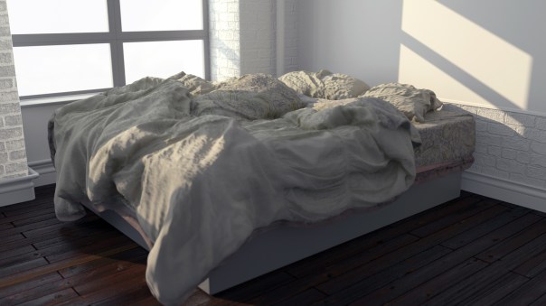
Daniel Morrison has some great 3D scans available for free here. Below is an Arnold render of his disheveled bed scan (video here).


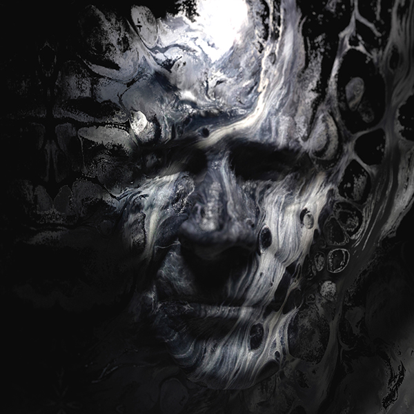
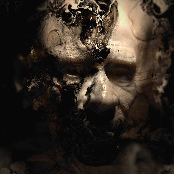
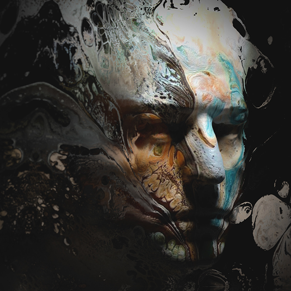
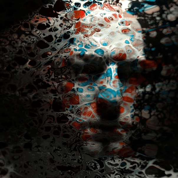
In this tutorial we will explore how to create an abstract, painterly effect applied to a head scan model to produce a ghostly looking portrait. In this tutorial we will specifically use the alSurface shader to produce this effect. Arnold can make use of 3rd party shaders such as the alShaders by Anders Langlands. This collection of shaders will need to be installed prior to starting this tutorial. Further examples using this technique can be found here.
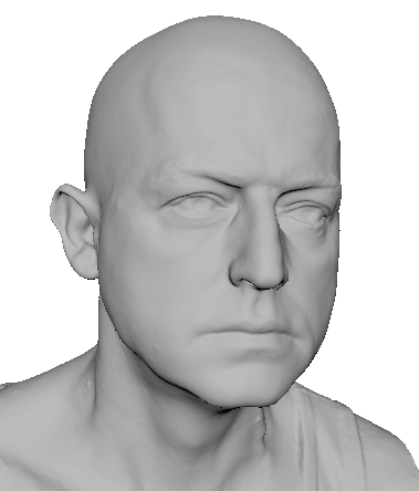
This tutorial makes use of this free head scan, kindly provided by Ten24.info.


Ensure that you disable ‘Opaque‘ for the polygon plane otherwise the refractive texture will not work correctly.

The direction that the the plane is facing in can have a large effect on the rendered result. The images below show the difference when rendering with the normals pointing inwards vs outwards.
 Normals facing outwards (left). Normals facing inwards (right).

The refractive plane has same file texture but is connected to Transmission and Backlight Color.

In most cases setting the Projection Type to Perspective works best for this effect to work. However, it is also possible to get some interesting results by using some of the other texture projection methods.

 Projection Type: None, Ball, Cubic, Spherical.
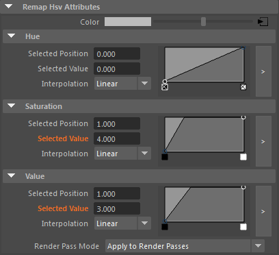
You can use a node such as the Remap HSV to give more control over the effect the texture map has on the Transmission IOR. The animation below shows the effect of the Remap HSV ‘Value’ attribute being animated from 1 to 5.
Careful positioning of the camera should be ensured otherwise the illusion will be broken. This can be seen in the animation below, where the camera has been rotated too far.

Increasing the amount of Transmission Roughness can help to soften the refractive effect. However, increasing this value too much can make the refractive effect appear too soft. Ensure that you have enough Refraction Samples when using Transmission Roughness. In this case a value of 4 was used.

Transmission Roughness: 0, 0.5, 1
You could also try adding some Volume Scattering to the scene to add some more integration of the head model with the background texture. Be warned however, that this technique can be prone to noise when using bright light sources and high specular values. This can be minimized by increasing the Specular Roughness for the head shader.

Same projected texture map connected to the Volume Scattering Color


Enabled (left). Disabled (right).
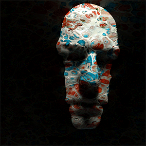
Converting the final rendered image to black and white in Photoshop (Image> Adjustments> Black and White) can also yield some interesting results. The images below show some of the effects available.

 Default, High contrast blue filter, Infrared, Maximum White
That concludes this tutorial on how to create an abstract refractive effect using the alSurface shader. You can also try this technique using different shaders and textures to get many interesting effects. The key is to just experiment with it and see what happens. You may be surprised by the results!
Flipped Normals have a free studio lighting scene available for rendering with Arnold for Maya. I highly recommend the full scene as a quick and easy way to light your models realistically using Arnold for Maya.

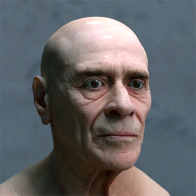
This ‘making of’ tutorial covers how to deform a head model into a surreal shape using the L3 Deformer plugin from Lightstorm3D (purchase required). This toolset is a collection of advanced deformation nodes and utilities for Maya. We will focus on the Collision Deformer in this tutorial. We will then move onto shading and lighting the head model to create a convincing photographic portrait look to our render. We will use the alSurface shader to add skin shading to the model with Arnold. Arnold can make use of 3rd party shaders such as the alShaders by Anders Langlands. This collection of shaders will need to be installed prior to starting this tutorial. Further examples using this technique can be found here.
This tutorial is divided into the following sections:


Requirements
Before you start this tutorial ensure that you have downloaded and installed the following files:
|
Make sure that the L3 Deformer plugin is installed correctly and loaded in the Maya Plug-in Manager before starting this tutorial.
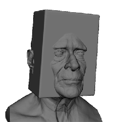
The Collision Deformer allows you to collide objects with polygon geometry, using projected collisions such as directional, concentrical and cylindrical.


The Collider node comes with some extra attributes aside from specifying the type of projection. You can choose between inward and outward projection for concentrical and cylindrical projections. You can also specify which side of a polygon to consider during collision detection (frontal, posterior or both). Soft depth and resistance attributes simulate the effect of soft collision geometry that can be compressed to some degree.
In this tutorial we will use the default concentrical collider setting, but we will alter the Soft depth and resistance values to achieve a smoother deformation effect.

The deformation effect currently looks too angular. We will need to change some of the default Collision Settings to give a softer merge between the head and the cube.

| Remember to convert your textures to .tx format using the TX Manager for more efficient rendering. You should use .tx files for everything (except with the aiSkydome and Quad lights). |


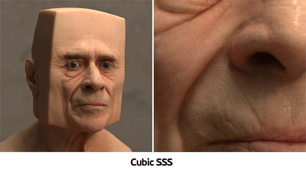
Below you can see the difference when rendering with the SSS modes: Cubic and Directional. The difference is subtle, but Directional SSS is generally recommended for skin as it has less of a ‘waxy’ appearance.


For final rendering increase all light Samples to 3 and increase Camera (AA) to 5 or 6. The SSS looks a little noisy with SSS Mode set to Directional using the default settings. Try increasing the SSS to 3 or 4 for the final render. Beware that increasing SSS samples can have a large impact on render time.

Applying Auto Tone to the image in Photoshop adjusts the tonal values and gives a more pleasing ‘photographic’ look to the render. Remember to convert the image to 8-bit prior to using Auto Tone.

That concludes this making of tutorial. Why not have a go at producing some bizarre and surreal head shapes using this technique!

Very honored to receive Creative Commission’s November’s Album Cover of the Month for the cover of Kateboy‘s album ‘One’.


You must be logged in to post a comment.